Download Images Library Photos and Pictures. Electrical Diagram Ammeter Renault Wiring Diagrams Pdf Begeboy Wiring Diagram Source Draw A Labelled Diagram Of Electric Circuit Comprising Of A Cell A Resistor An Ammeter A Voltmeter Brainly In A Student Made An Electric Circuit Shown Here To Measure The Curre Simple Electric Circuit Set Up Evan S Space
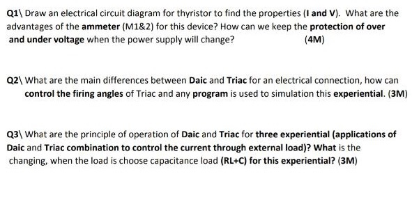
It is always connected in series with the circuit in which the current is to be measured. Draw a diagram to illustrate your answer.
. Draw A Circuit Diagram Of An Electric Circuit Containing A Cell A Key An Ammeter A Resistor Science Electricity 11283069 Meritnation Com How To Measure Current On An Electronic Circuit Dummies Ohm S Law Conductor Insulator Electric Circuit Ammeter Voltmeter
 Diagram Digital Voltmeter Wiring Diagram Full Version Hd Quality Wiring Diagram Phasediagramcalculator Osterianonnagina It
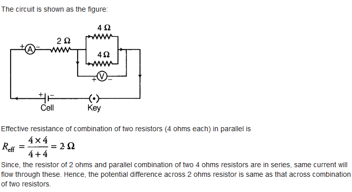
Diagram Digital Voltmeter Wiring Diagram Full Version Hd Quality Wiring Diagram Phasediagramcalculator Osterianonnagina It Will the potential difference across the 2 w resistor be the same as that across the parallel combination of 4 w resistors.
. This will help us to improve better. Or quad sfrac i g i i g g. The ammeter is usually connected in series with the circuit in which the current is to be measured.
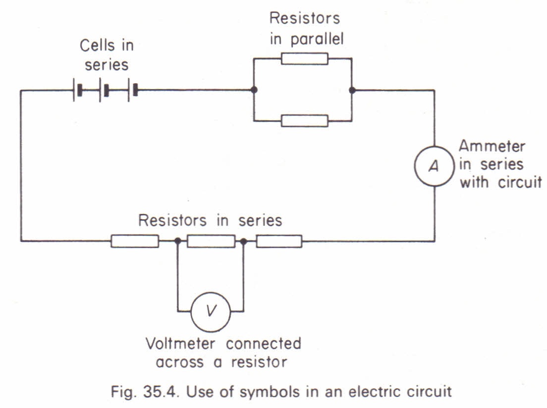
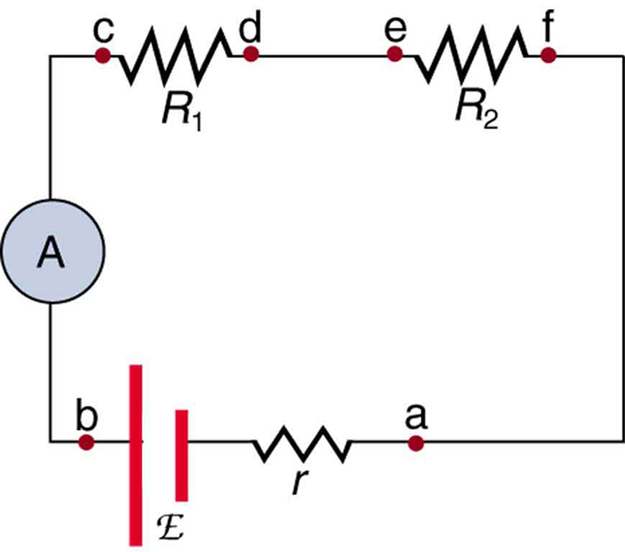
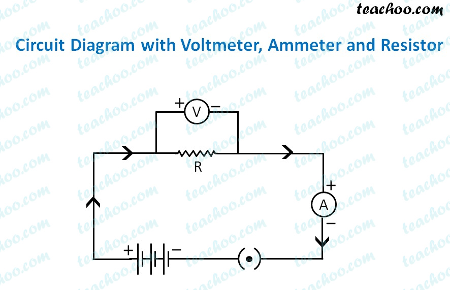
An ammeter measures current and a voltmeter measures a potential difference. Study the circuit diagram and redraw it after making all corrections. How is it connected in a circuit.
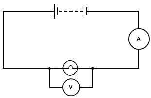
Draw a circuit diagram of an electric circuit containing a cell a key an ammeter a resistor of 2 w in series with a combination of two resistors 4 w each in parallel and a voltmeter across the parallel combination. Once this device is connected in series in the circuit then the total measurand current will flow through the meter. So voltage drop must be minimal.
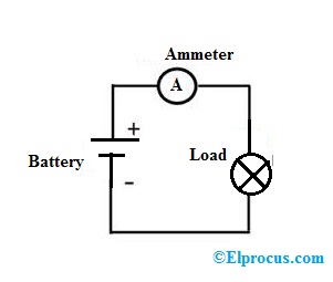
So the loss of power. View answer extra question 12 draw a circuit diagram of an electric circuit containing a cell a key an ammeter a resistor of 2 w in series with a combination of two resistors 4 w each in parallel and a voltmeter across the parallel combination. An ammeter is a device used for the measurement of electric current.
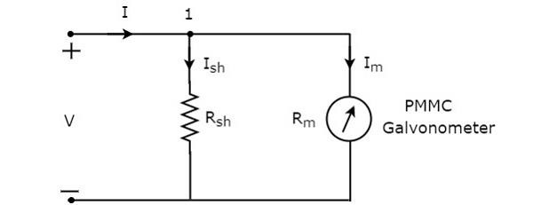
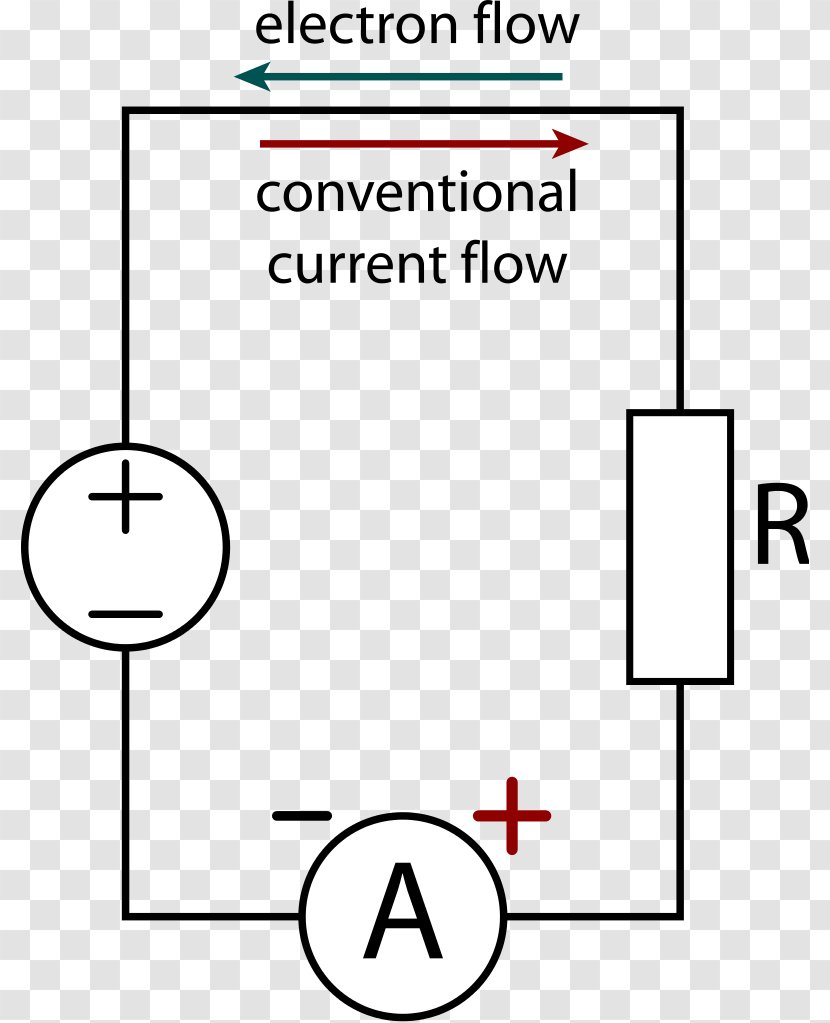
An ammeter usually has low resistance so that it does not cause a significant voltage drop in the circuit being measured. An ammeter from ampere meter is a measuring instrument used to measure the current in a circuitelectric currents are measured in amperes a hence the name. Here g is resistance of galvanometer and i g is current required to produced full scale deflection of current.
To measure electric current in a circuit ammeter must be connected in series because in series connection ammeter experiences the same amount of current that flows in the circuit. Electrical circuits series if we include a battery as the voltage source the series circuit would look like this. The capital a represents the ammeter in the circuit.
Some materials have low resistance and are conductors. C1 vbat c2 note that there is only. Here mathrm i 9 mathrm gleft mathrm i mathrm i mathrm gright mathrm s.
The construction of ammeter can be done in two ways like series and shunt. The following circuit represents the basic circuit diagram and the connection of the ammeter circuit in series and parallel are shown below. Ammeter is designed to work with a small fraction of volt.
Upvote6 how satisfied are you with the answer. Electric circuits can be series or parallel.
 Ammeter And Voltmeter Circuit Diagram Current Electricity 12 Jee Neet
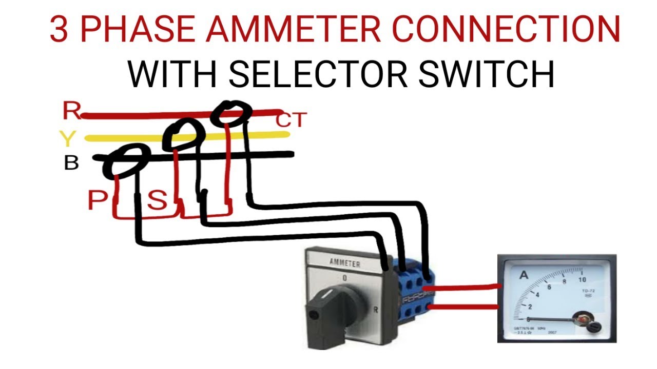 3 Phase Ammeter Connection With Selector Switch Youtube
 Draw A Circuit Diagram Of An Electric Circuit Containing A Cell A Key An Ammeter A Youtube
 Series Circuits Series And Parallel Circuits Siyavula
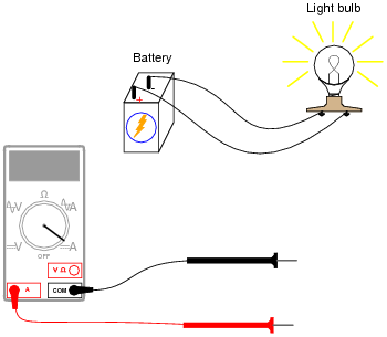
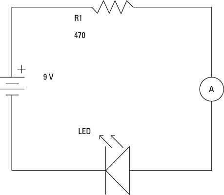 How To Measure Current On An Electronic Circuit Dummies
 Solved Q1 Draw An Electrical Circuit Diagram For Thyrist Chegg Com
 Measuring Resistance With A Voltmeter And An Ammeter Iopspark
 Electrical Meters
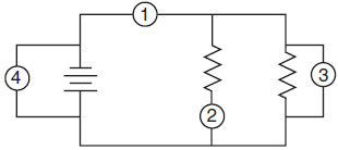
 A Draw A Ammeter Symbol On This Circuit Diagram Where It Would Measure The Current Through The Electric Motor Teachernotes4u
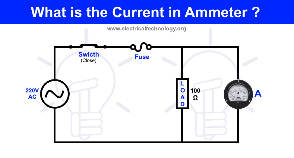 What Is The Current In Ammeter Connected In Parallel
Ammeter Vs Voltmeter Difference Between Ammeter And Voltmeter Electrical Academia
 Dc Ammeters Tutorialspoint
 Basic Ammeter Use Worksheet Basic Electricity
 Draw A Labelled Diagram Of Electric Circuit Comprising Of A Cell A Resistor An Ammeter A Voltmeter Brainly In
 What Is A Circuit Diagram Draw The Labelled Diagram Of An Electric Circuit Comprising Of A Cell A Youtube
 Electric Circuit Use Of Ammeters And Voltmeters Physics Homework Help Physics Assignments And Projects Help Assignments Tutors Online
 Draw A Circuit Diagram Of An Electric Circuit Containing A Cell A Key An Ammeter Youtube
Http Resource Download Wjec Co Uk S3 Amazonaws Com Vtc 2016 17 16 17 1 8 Discovering Electronics Chapter 2 Digital Pdf
 Ammeter Working Principle Circuit Diagram Types And Applications
 Voltmeters And Ammeters Boundless Physics
Principle Scheme Of The Electrical Circuit Used Including A Download Scientific Diagram
 Electric Circuit Diagram Symbol Open And Closed Circuit Teachoo
 Ammeter Electric Current Wiring Diagram Wikipedia Electrical Network Flow Transparent Png
 Draw A Circuit Diagram Of An Electric Circuit Containing A Cell A Key An Ammeter A Resistor Science Electricity 11283069 Meritnation Com
Https Encrypted Tbn0 Gstatic Com Images Q Tbn And9gcqjnwsawqahrvexr9noo3guispkqrgjk 8f98isem8gixmb5wnx Usqp Cau
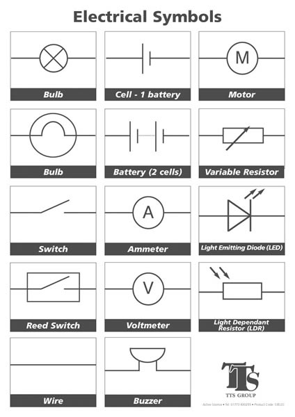
 Electrical Wiring Diagram Legend Http Bookingritzcarlton Info Electrical Wiring Diagram Legend Electrical Wiring Diagram Electrical Symbols Car Alternator


0 comments:
Post a Comment